Project Overview
Samantha Knight and I designed and assembled this Bluetooth thumb keyboard for our EGR 436 final project at Grand Valley State University. The idea was to provide portable text input when a full-size keyboard is inconvenient—for example, while standing, moving between workstations, or working at a bench.
The keyboard brings a 71-switch key matrix, an STM32L476 microcontroller, rechargeable battery operation, Bluetooth communication, and battery-voltage monitoring together on a custom PCB. The final report was submitted on April 27, 2026.
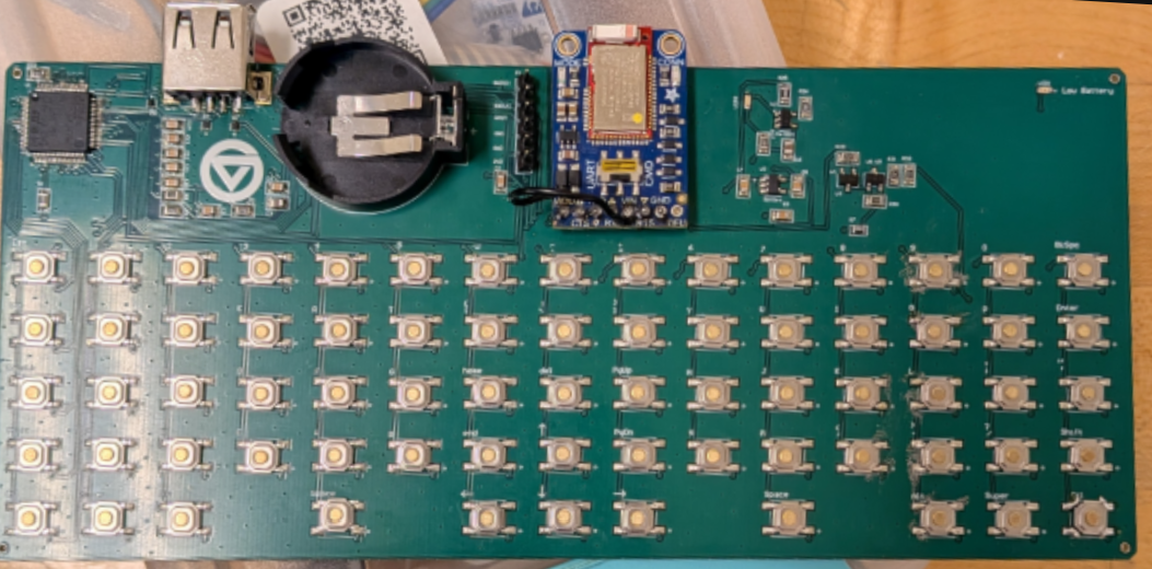
Source code availability: At the time of writing this project page, I no longer have the source code. This writeup is based on the final report and the remaining photograph and schematics; it does not include a code download or a verified reconstruction of the firmware.
Design Goals & Results
The goal was a compact keyboard for two-thumb typing, with wireless connectivity and a rechargeable battery. USB was intended to provide both charging and an optional wired keyboard connection. The course also required a custom PCB and a microcontroller integrated at the chip level and programmed in place.
The final report documents the following results:
| Feature | Result |
|---|---|
| Custom PCB and integrated microcontroller | Designed and assembled |
| 71-switch key matrix | Functional after switch-orientation rework |
| Wireless communication | Implemented using a Bluefruit UART-Friend module |
| USB battery charging | Implemented using an STC4054GR charge-management IC |
| Battery-voltage monitoring | Implemented through the STM32 ADC and a switched sensing circuit |
| Battery-current monitoring | Not implemented |
| Wired USB HID keyboard operation | Hardware incorporated; software was not fully functional or validated by the deadline |
| Dedicated power switch and enclosure | Identified as improvements for a future revision |
Reliable, low-latency input and long battery life were design goals. The surviving report does not provide measured latency, runtime, or power-consumption results, so those are not presented here as verified performance figures.
System Architecture
The STM32L476 manages the keyboard inputs and battery monitoring. The switch matrix provides the key inputs, while the Bluefruit UART-Friend handles the wireless link. Using a dedicated Bluetooth module reduced the amount of custom wireless development needed within the project timeline.
A USB connection supplies the battery-charging circuit. The design also included a USB data interface for the STM32’s USB OTG functionality, with the intent of supporting wired HID keyboard operation. That data path remained incomplete in software; successful USB charging did not mean that wired keyboard communication was finished.
The report describes matrix scanning, debouncing, and power-state management as parts of the firmware design. With the source code no longer available, I cannot document the exact implementation or configuration of those routines.
Key Matrix & Switch Rework
The keyboard uses 71 tactile switches arranged in a row-and-column matrix. This lets the controller identify key inputs through shared matrix connections rather than assigning a separate input to every switch.
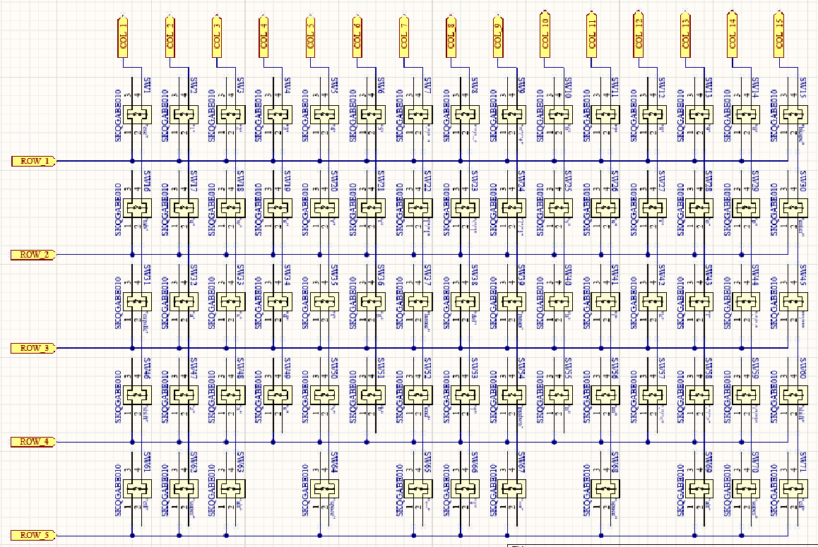
The switch symbol became the largest assembly problem. We used a symbol downloaded from Ultra Librarian to determine which terminals were permanently connected and which were connected only when the switch was pressed. The symbol did not match the physical switch’s terminal behavior.
As a result, all 71 switches were installed in the wrong orientation. Each had to be rotated 90 degrees and resoldered. The rework restored the key matrix’s functionality, but it consumed time that could have gone toward software development and testing.
The lesson was to verify the physical component before committing to a full assembly. A continuity check on a sample switch would have exposed the mismatch between the library symbol and the actual terminals.
Battery Charging & Voltage Monitoring
The STC4054GR charging IC provides USB charging for the rechargeable battery and supports a charging-status LED. A separate low-battery indicator alerts the user when the battery voltage is low.
The voltage-sensing circuit uses an N-channel AO3400A MOSFET and a P-channel AO3401A MOSFET to switch the battery measurement path. The STM32 enables the circuit through a GPIO signal, then uses its ADC to measure the divided battery voltage.
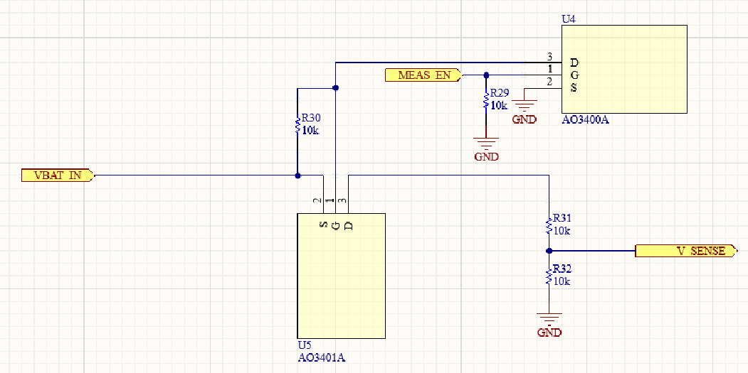
In the schematic, R31 and R32 are both 10 kΩ. Their equal values divide the enabled battery voltage approximately in half:
Switching the measurement path allows the controller to enable the divider when a reading is needed. Battery voltage was monitored, but battery current was not. The report does not preserve the ADC calibration details or the low-battery threshold, and the missing code prevents checking those settings.
USB Development & Remaining Work
The USB interface was designed around the STM32L476’s USB OTG peripheral. The hardware included the connections needed for the intended wired keyboard interface, but software development barriers prevented that feature from reaching a fully functional state before submission.
Completing and testing USB HID would be a priority for a future revision. It would allow the same device to operate as a wired keyboard as well as a wireless one. That remains a proposed improvement rather than a capability demonstrated by this project.
Assembly & Usability
The assembled board demonstrates the core keyboard concept, but the physical design still had room for improvement. A dedicated power switch was overlooked, and the project did not reach the fixture or enclosure stage.
A future version would include a power switch and a fixture designed around grip, key access, and protection of the electronics. These changes would make the board easier to handle and more convenient to use as a portable device.
Lessons Learned
- Verify library symbols against real components. A common source for a symbol is not a substitute for checking its pin behavior.
- Test a small portion before populating the entire board. The switch-orientation error multiplied across all 71 keys and required substantial rework.
- Separate hardware readiness from software completion. The USB hardware and charging functionality were present, while USB keyboard communication was still incomplete.
- Plan the physical interface alongside the electronics. A power switch, enclosure, and comfortable grip are part of making a handheld device usable.
The project produced a working custom-PCB keyboard with wireless communication, rechargeable operation, and battery-voltage monitoring. The switch rework and unfinished USB interface were also part of the result, and they shaped what I would change in a second revision.