Project Overview
During my sophomore year, John Bushman and I built this Whack-A-Mole game for our EGR 227 final project at Grand Valley State University in December 2023. The goal was to bring several microcontroller peripherals together into one working system: a screen to show the moles, a keypad to hit them, buttons to control the game, an LED for score feedback, and a servo to show the time remaining.
Press Start, wait through the countdown, and match the mole’s position on the screen to a key on the keypad. Each hit adds ten points. A round lasts about fifteen seconds, with the servo moving through its sweep as time passes. At the end, the LCD displays the three most recent scores.
We shared the programming and report work equally. Alongside the required electronics and firmware, we added a 3D-printed enclosure and chose an LCD character to represent the mole. The result was a game that could be picked up and played without handling a loose collection of components.
Playing the Game
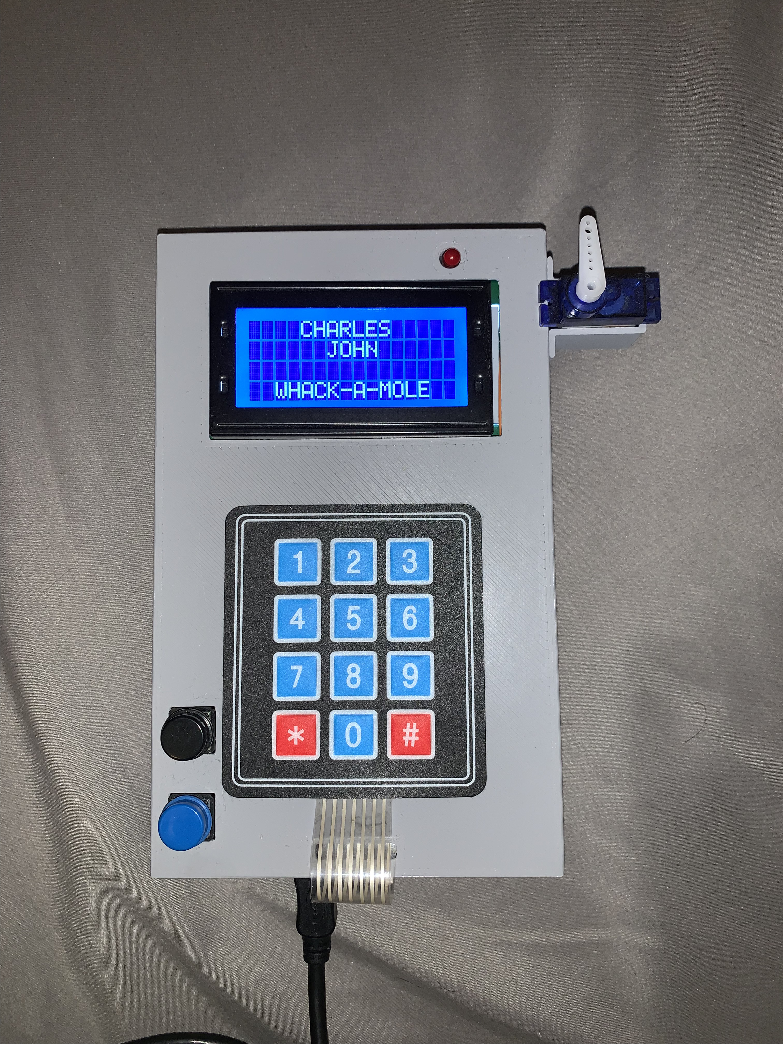
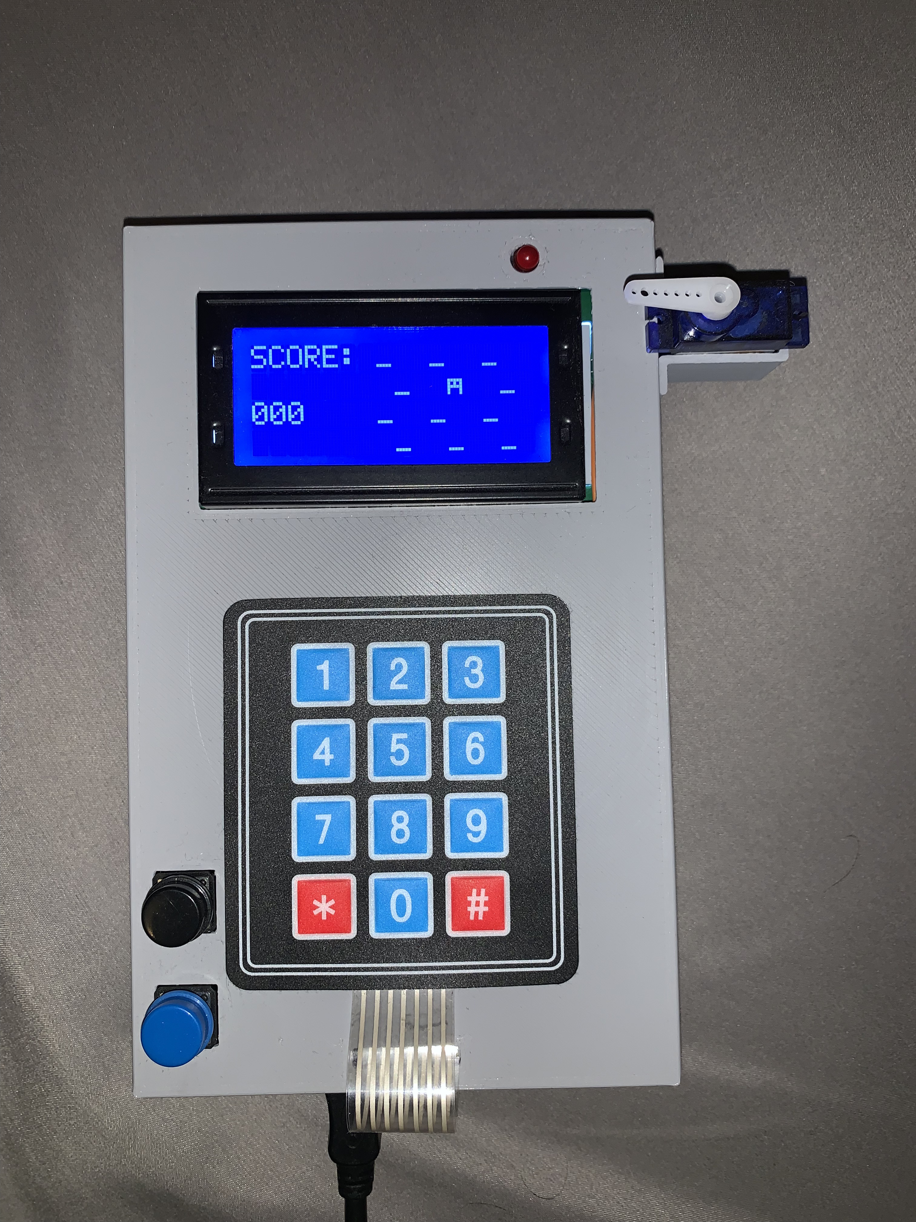
The 16 × 4 character LCD provides the interface. The startup screen identifies the project, the countdown prepares the player, and the gameplay screen places the score beside a four-row, three-column grid of mole positions. That layout corresponds to the physical keypad. A second push-button lets the player bring up the score sheet while the game is idle.
Enclosure Design & Assembly
The enclosure was an extra part of the project, designed to hold the electronics and snap shut with a compliance fit. The front panel provides openings for the LCD, keypad connection, and push-buttons, while the servo sits at the side where its motion is visible.
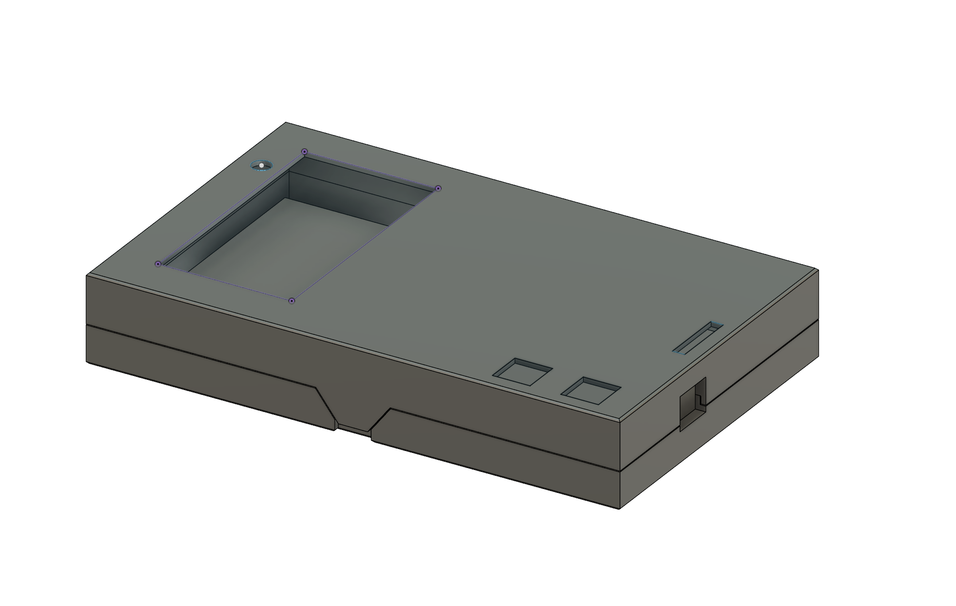
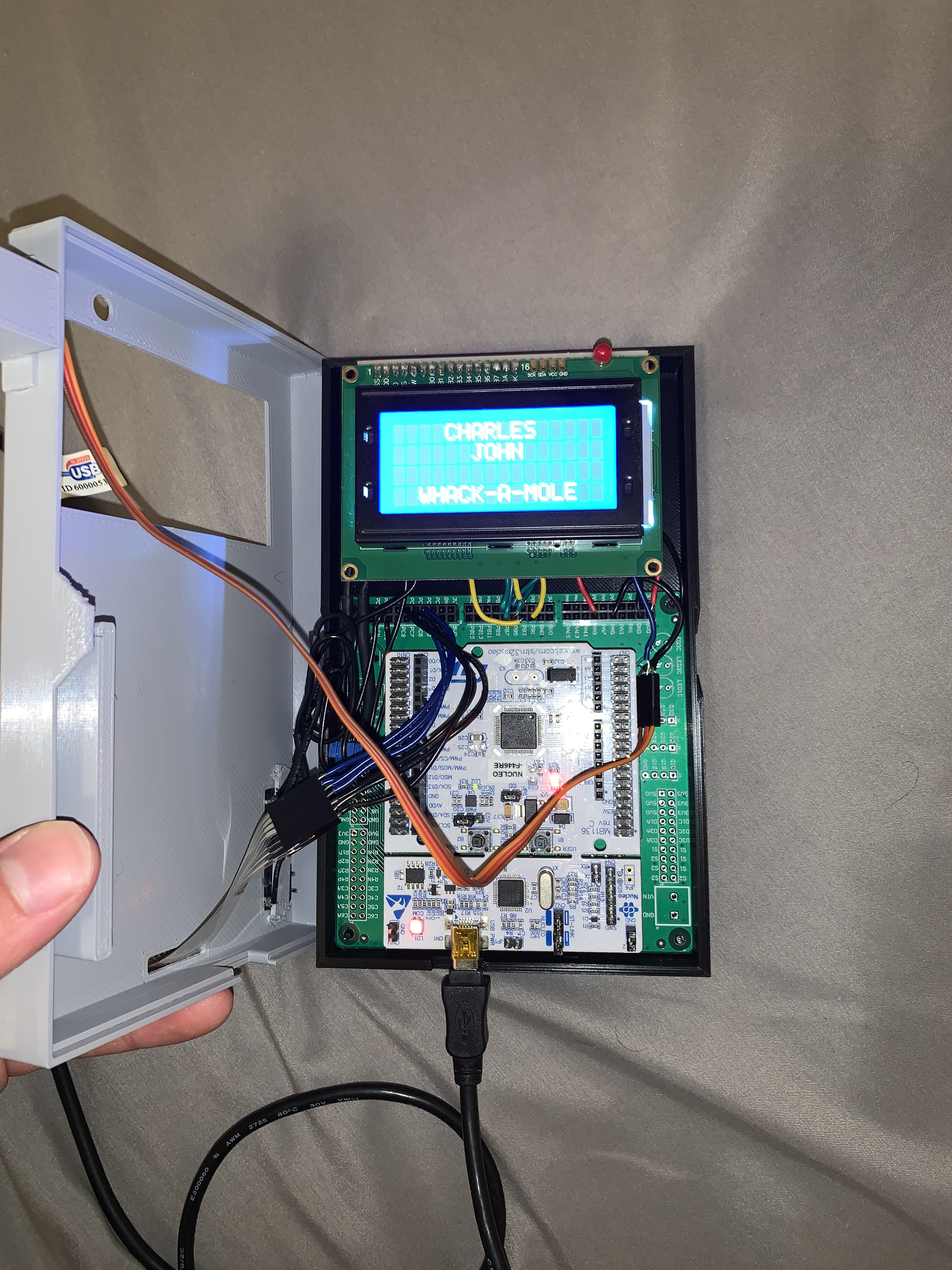
The CAD model accounted for the components, but the case was too thin for comfortable wiring and assembly. Fitting everything inside took almost as much time as programming the game. The enclosure worked, but a deeper case and more room around the connections would have made assembly easier. This was a useful reminder to design for the process of putting a device together as well as its finished appearance.
Hardware & Connections
The controller is an STM32F446RE Nucleo board, programmed in C using Keil µVision 5. The main peripherals are a 16 × 4 LCD, a 4 × 3 matrix keypad, two momentary push-buttons, a red LED, and an SG90 servo. A potentiometer sets the LCD contrast.
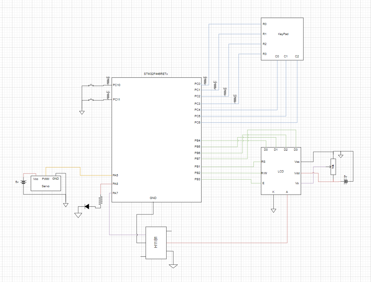
The following table summarizes the connections used in the archived firmware. The report’s schematic places the LED on PA7; the firmware configures PA9, so the table follows the code for that connection.
| Peripheral | STM32 connection | Purpose |
|---|---|---|
| Start button | PC10 / EXTI10 | Begin a round and seed the random sequence |
| Score button | PC11 / EXTI11 | Display recent scores outside gameplay |
| Keypad | PC0–PC3 rows, PC4–PC6 columns | Read the player’s selected mole position |
| LCD | PB1–PB3 control, PB4–PB7 data | Drive the display using a four-bit interface |
| Servo | PA5 / TIM2 CH1 | Generate the PWM countdown indicator |
| Red LED | PA9 | Indicate a score matching the maximum in the recent-score array |
| Game timer | TIM3 CH1, with PA6 configured for that channel | Supply the periodic timing interrupt |
Firmware Architecture
The report’s state diagram describes the player’s path through startup, countdown, gameplay, and score display. The code implements three top-level states: START, game, and SCORE. Countdown and active play are two phases within game, separated by the elapsed-time counter.
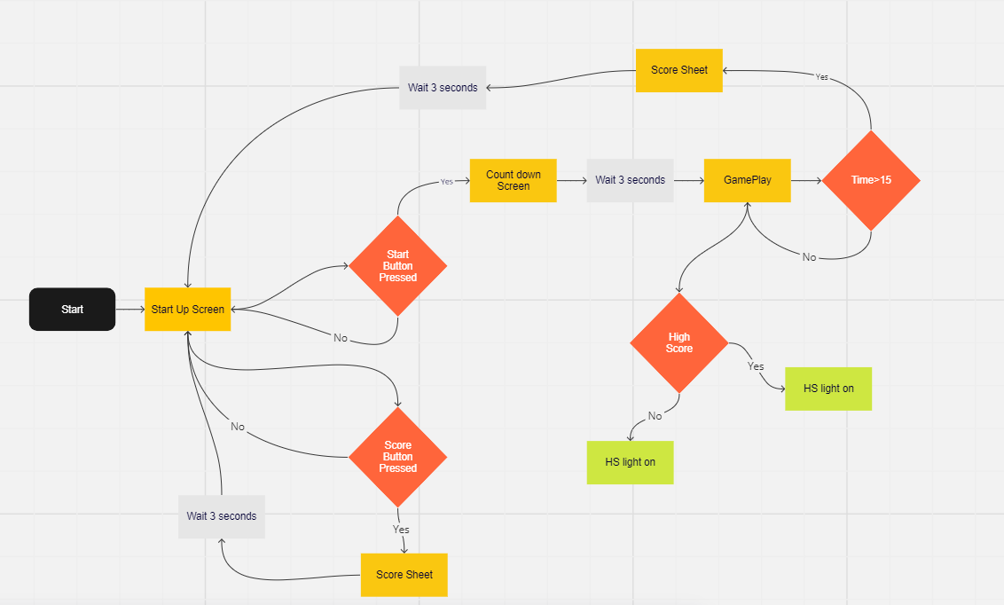
In START, the firmware displays the title screen and resets the servo position. A falling-edge interrupt from the Start button shifts the score history, resets the elapsed time, and enters game. After the countdown, the program begins checking keypad input against the active mole. When the round ends, it enters SCORE, displays the score sheet, and returns to startup after the display interval.
The score button uses the same external-interrupt handler. Its state check prevents a score-sheet request from interrupting an active round. The original diagram repeats “HS light on” on both high-score branches; the actual LED comparison is described in the scoring section below.
LCD & Keypad Interaction
We reused an LCD library developed earlier in the semester and added functions for the startup, countdown, gameplay, and score-sheet screens. The driver sends each byte in two four-bit transfers, separating display commands from character data. A table of LCD addresses maps the mole grid to screen positions.
The mole uses the LCD character code 0xFC, selected from the display’s character set. Empty positions are represented by underscores. This changes the displayed character without defining a new bitmap in character-generator RAM.
The keypad driver scans one column at a time and reads the four row inputs. Its decoded result is compared with the active mole’s index. The LCD function converts a randomly selected row and column to that index:
int moleAppear(int randRow, int randCol) {
    int mole = 0;
    commandWrite(mole_array[randRow][randCol]);
    delay_ms(10);
    dataWrite(MOLE);
    mole = (randRow * 3) + (randCol + 1);
    return mole;
}
This excerpt comes from the archived LCD.c. It connects the visual location on the LCD to the value checked against the keypad.
Mole Placement & Scoring
The Start-button interrupt calls srand(sec) before resetting the elapsed-time counter. The amount of time spent waiting to start therefore affects the sequence of mole positions. Each timing interrupt selects a row with rand() % 4 and a column with rand() % 3.
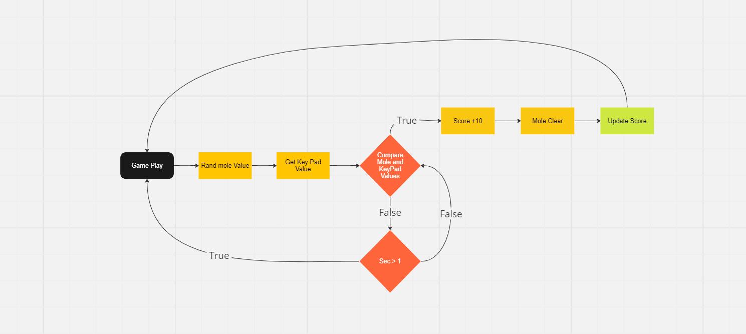
A matching key adds ten points to SCORES[0], clears the mole, and refreshes the displayed score. The timer clears the hit flag for the next interval. The three-element score array shifts when a new round begins, preserving the two preceding scores alongside the current one.
The LED comparison finds the maximum within that array and turns on the LED when the current score equals it. Ties count, and the comparison includes the current score; it is not a separate all-time high-score record. Scores remain in RAM and reset when power is removed.
Timing & Servo Control
TIM3 provides the approximately one-second timing interrupt. Its handler increments sec, updates the mole row and column, and adjusts the servo position during active gameplay. TIM2 independently generates the servo PWM signal, designed around a 50 Hz period.
The relevant excerpt from the archived TIM3_IRQHandler is:
sec++;
flag++;
rows = RRAND;
cols = CRAND;
if (gameState == game && sec >= 3) {
    TIM2->CCR1 = (475 + ((sec - 3) * 128));
}
After the countdown, the compare value increases in steps as the round progresses. The servo’s movement gives the player a physical indication of elapsed time, alongside the LCD’s digital interface.
The timer interrupt provides the game’s timing reference, but the implementation also uses blocking LCD delays and keypad polling. It is a useful distinction: interrupt-driven timing did not make every part of the program nonblocking.
Integration & Lessons Learned
Splitting the program into separate pieces helped us develop the peripherals, but bringing those pieces together exposed differences in how we expected the main loop and shared variables to behave. Working through the program logic together was necessary to turn the individual functions into a complete game.
Three lessons stood out:
- Agree on interfaces before integration. Shared state, function behavior, and naming need to be understood by both contributors.
- Build reusable peripheral libraries. The earlier LCD and keypad work gave us a starting point and reduced the amount of setup code needed for this project.
- Leave room for assembly. Wires, connectors, and the order of installation need space beyond the dimensions of the components themselves.
The finished game brought together GPIO, external interrupts, timers, PWM, a character LCD, and keypad input in one enclosure. The most useful learning came from making those parts work together and then fitting the working system into a physical device.