Digital Monster Pet
A highly interactive embedded system of a simulated pet that reacts to user interaction
Introduction and Design Background
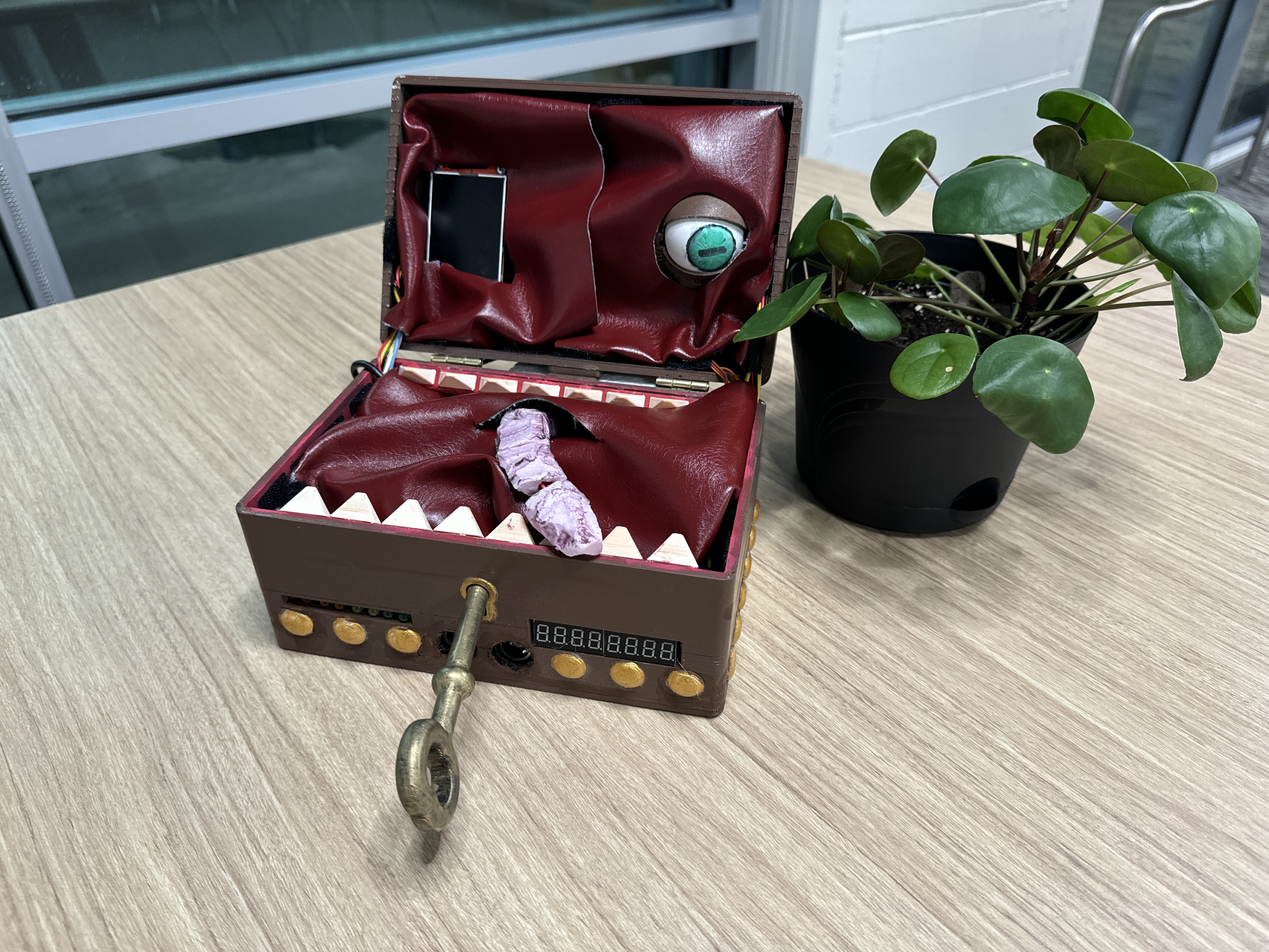
This project addresses the design challenge of creating an interactive system inspired by the mimic creature from fantasy games like Dungeons & Dragons and Dark Souls. The objective was to build a responsive, multi-functional system that combines creative inspiration with technical rigor, meeting customer expectations for engagement, precision, and functionality.
The solution leverages the STM32F446RETx microcontroller to integrate multiple sensors, actuators, and display technologies. Key components include a rotary encoder, ultrasonic proximity sensor, Hall effect sensor, LCD RGB graphic display, shift register, seven-segment display, and servo motor. These devices enable proximity detection, input handling, motion control, and visual feedback.
The design approach involved configuring hardware and software to manage sensor inputs, control actuators, and synchronize outputs. This includes employing efficient communication protocols and control algorithms to ensure a seamless and robust system. The following sections detail the design objectives, technologies used, and the approach taken to achieve the project’s goals.
System Architecture
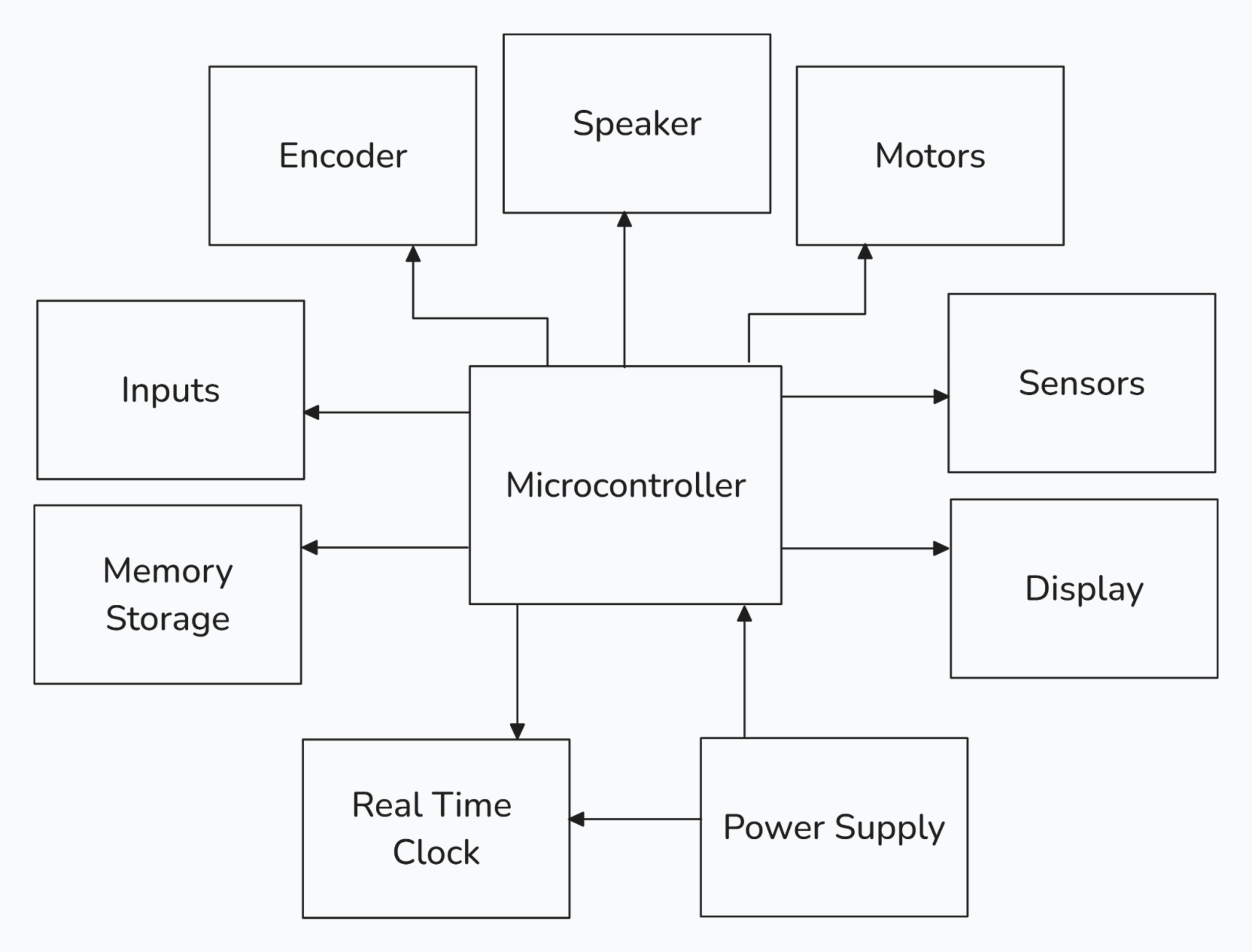
The hardware design for this project features a single STM32F446RETx microcontroller, serving as the central controller to manage all sensors, actuators, and peripherals. The system integrates various components through I2C and SPI communication protocols, enabling efficient data exchange and coordination between devices.
Hardware Design
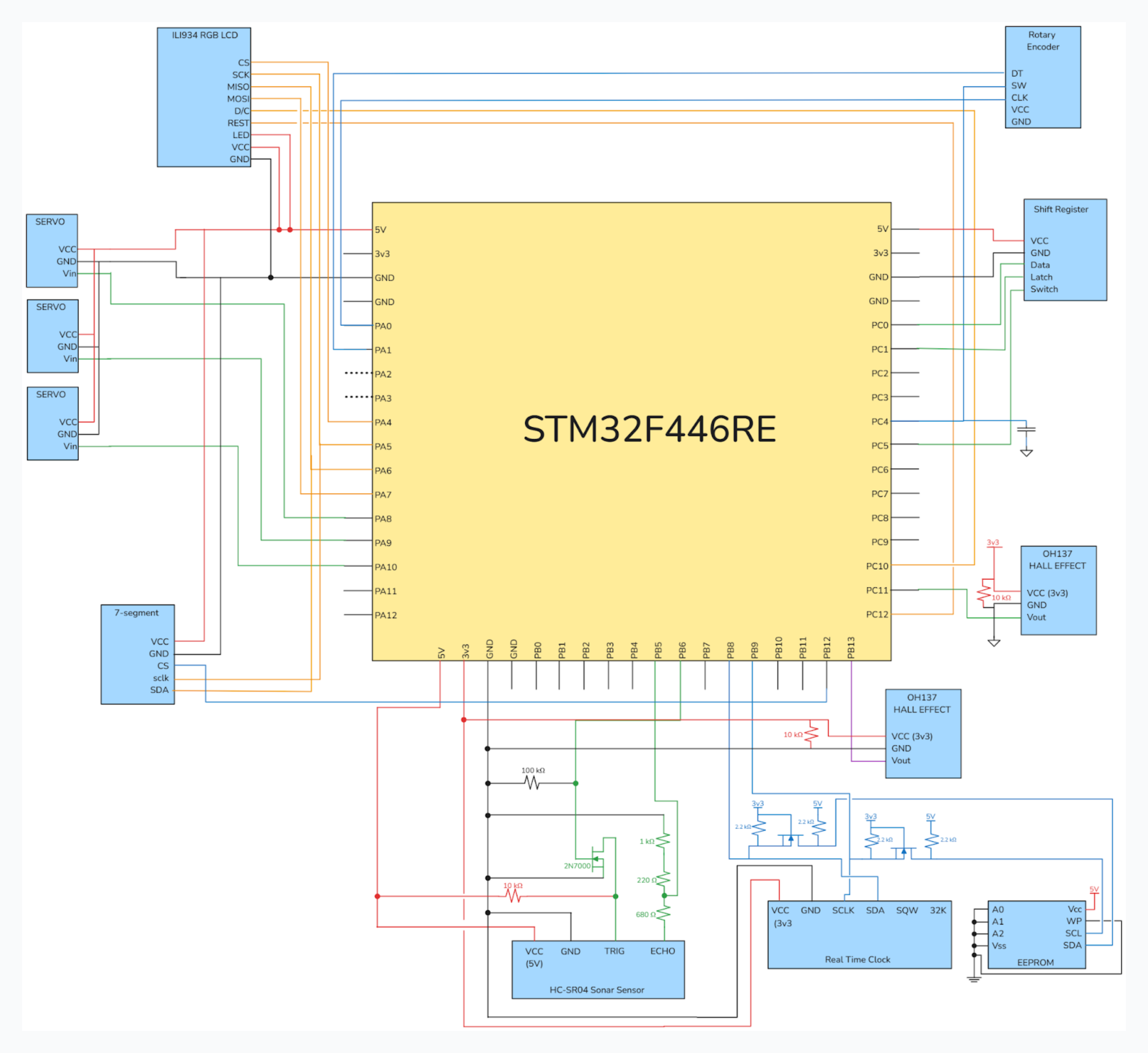
One of the special features of the design is the inclusion of a shift register IC to control a set of LEDs that visually display the health of the digital mimic, adding an interactive and dynamic element to the system. A speaker, paired with an LM386 audio amplification circuit, provides audio feedback to enhance user engagement.
For communication, the RTC and EEPROM share the I2C protocol, supported by a double-level shifter to handle both 5V and 3.3V logic seamlessly. This ensures compatibility and reliable operation between components with different voltage requirements. The seven-segment display and LCD RGB graphic display both utilize SPI for efficient and high-speed communication.
The hardware design balances functionality and creativity by combining these features into a system that is robust, responsive, and engaging.
Software Design
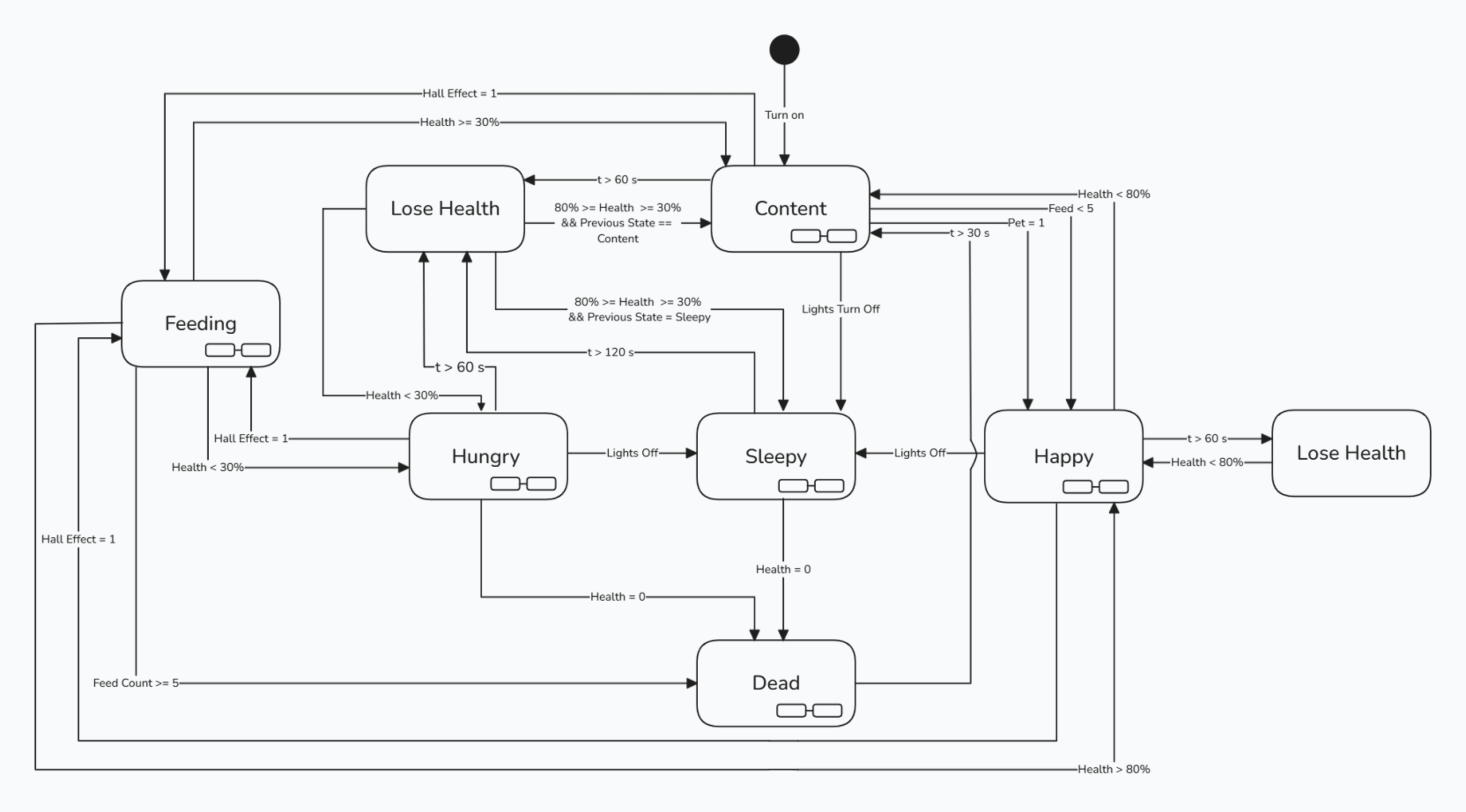
A switch must be turned on after the system has power. Once switched on, it will default to the “content” state, and its initial health value will be 70% of its maximum health value.
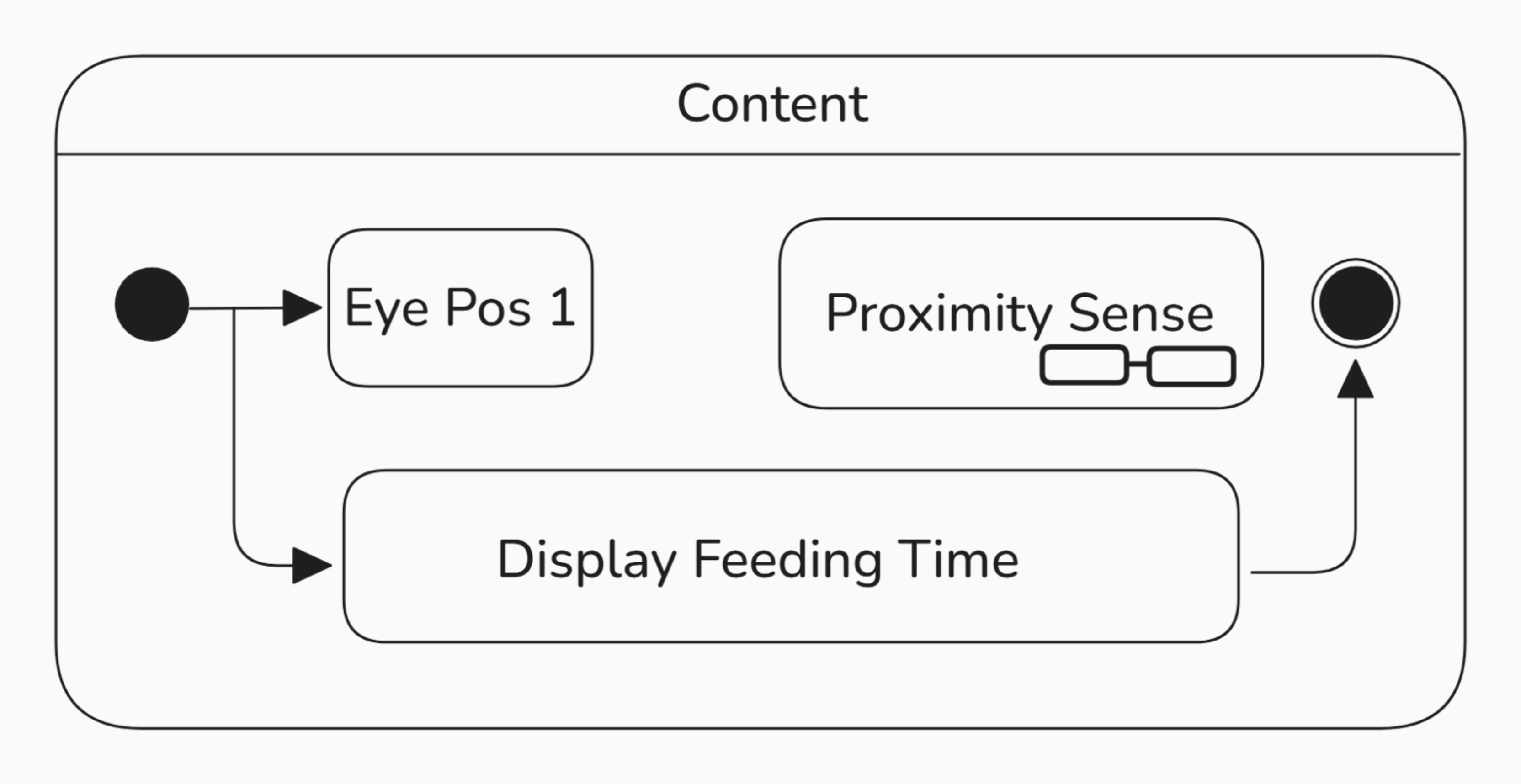
Within the content state, the monster’s eye position will be neutral. During the content state, the proximity sensor and hall effect sensors are checked for petting and feeding. The feeding time is also displayed.
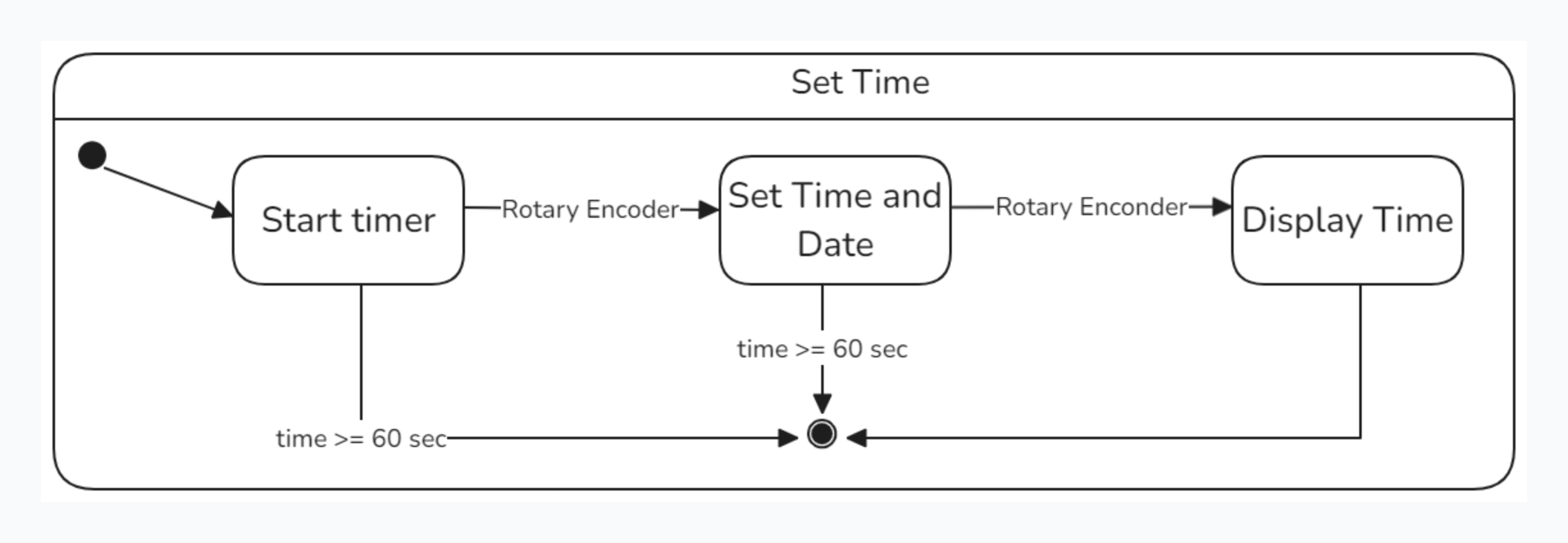
When setting the time, a timer is initially started, such that if no input is made within a minute, the action of setting the time will be canceled. The time is set using the rotary encoder to select time values displayed on the LCD. After the time is set, it will be displayed on the LCD and resume to its previous state. Also, within the content state, the proximity sensor will be checked periodically to see if a person is approaching the monster.
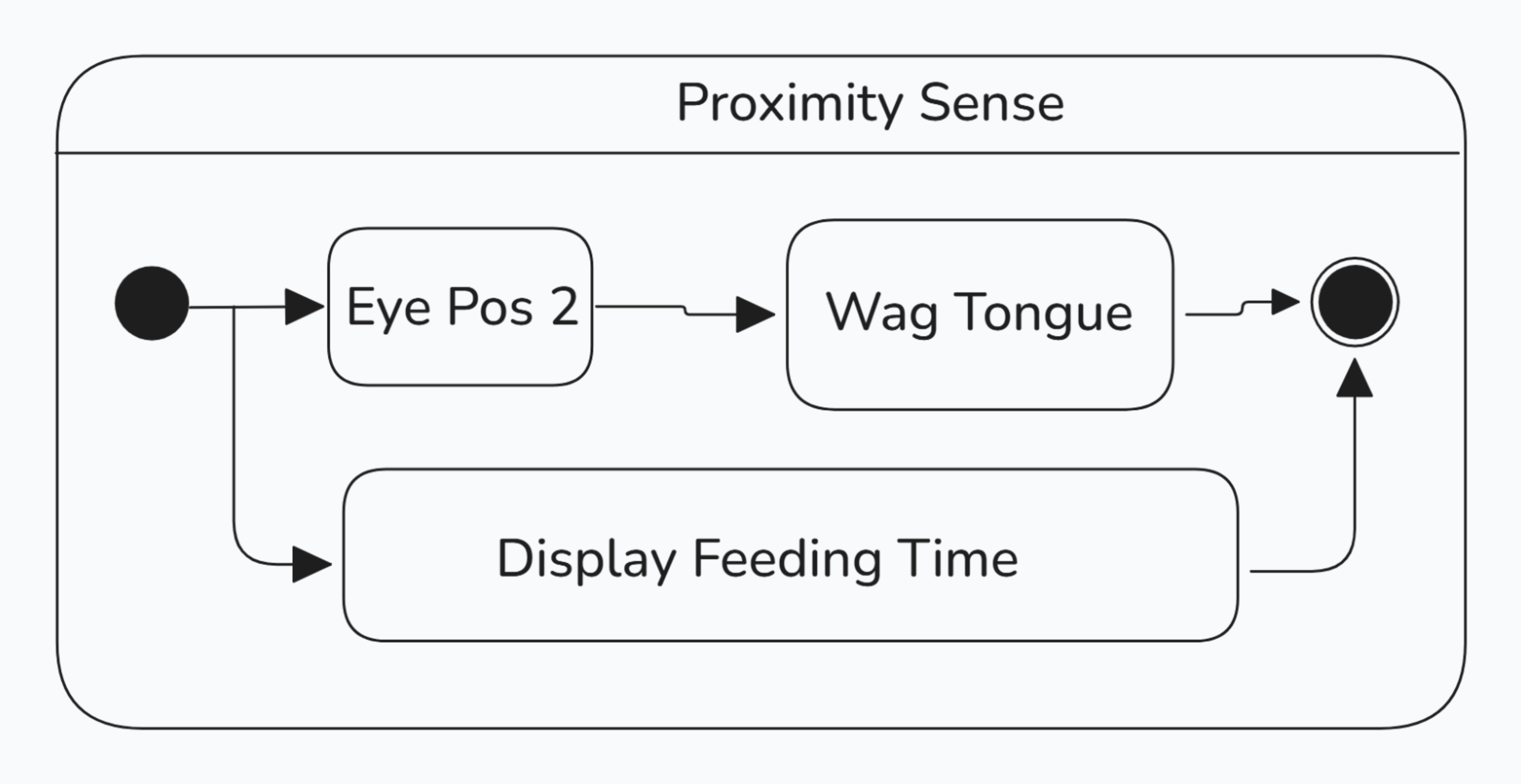
During the proximity check, the monster’s eye opens wide; if a person is in proximity, the monster begins to wag its tongue.
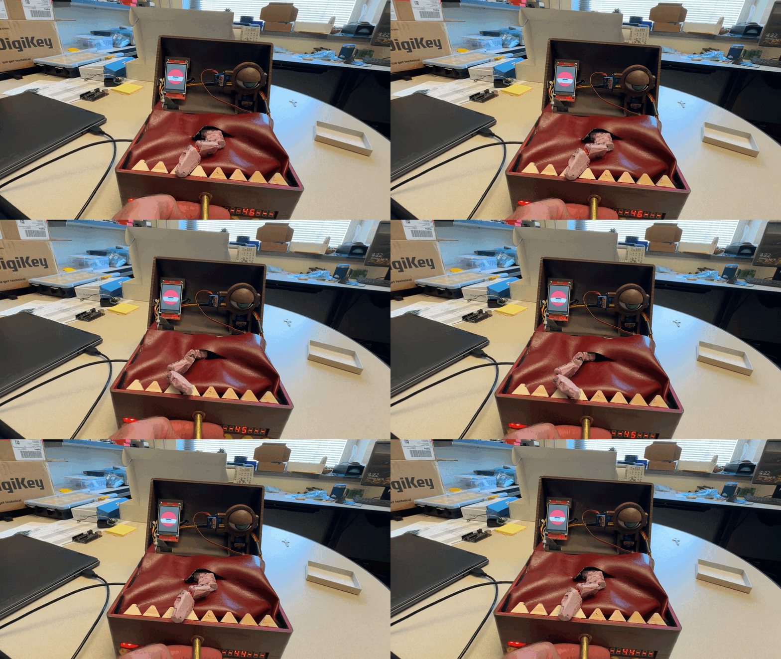
While in the content state, if a hall effect sensor is activated in the head, effectively ‘petting’ the monster, then the monster will transition to the Happy state. Additionally, if a hall effect sensor is activated in the mouth of the monster (‘feeding’ the monster), then the monster will transition to the happy state. The monster will stay in the Happy state while its health is above 80% of its maximum health.
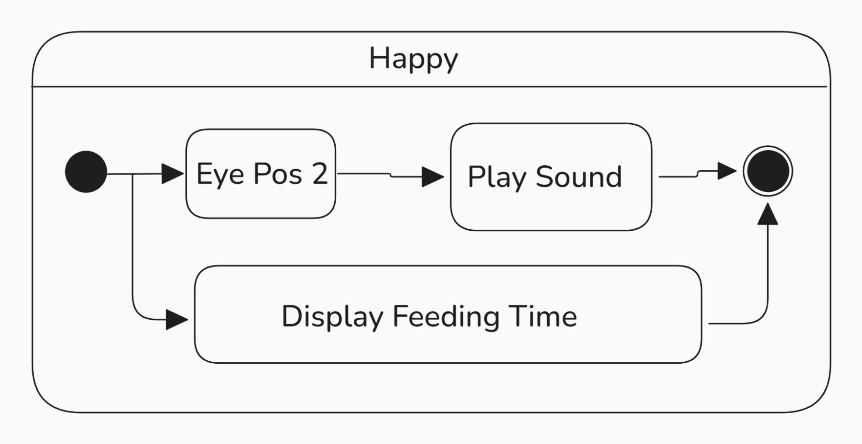
While in the Happy state, the monster’s mechanical eye will open wide. The monster will wag its tongue and play a sound.
Meanwhile, in the Content state, the health will drop by 10% of its maximum health every minute. If the monster’s health drops to zero, then the monster transitions to the Dead state. Another way the monster can transition to the dead state is by being fed more than 5 times while it is in the Happy State.

In the Dead state, the eye closes, the mouth changes to a neutral position, and a sound plays. Once the monster is dead, the system shuts down.
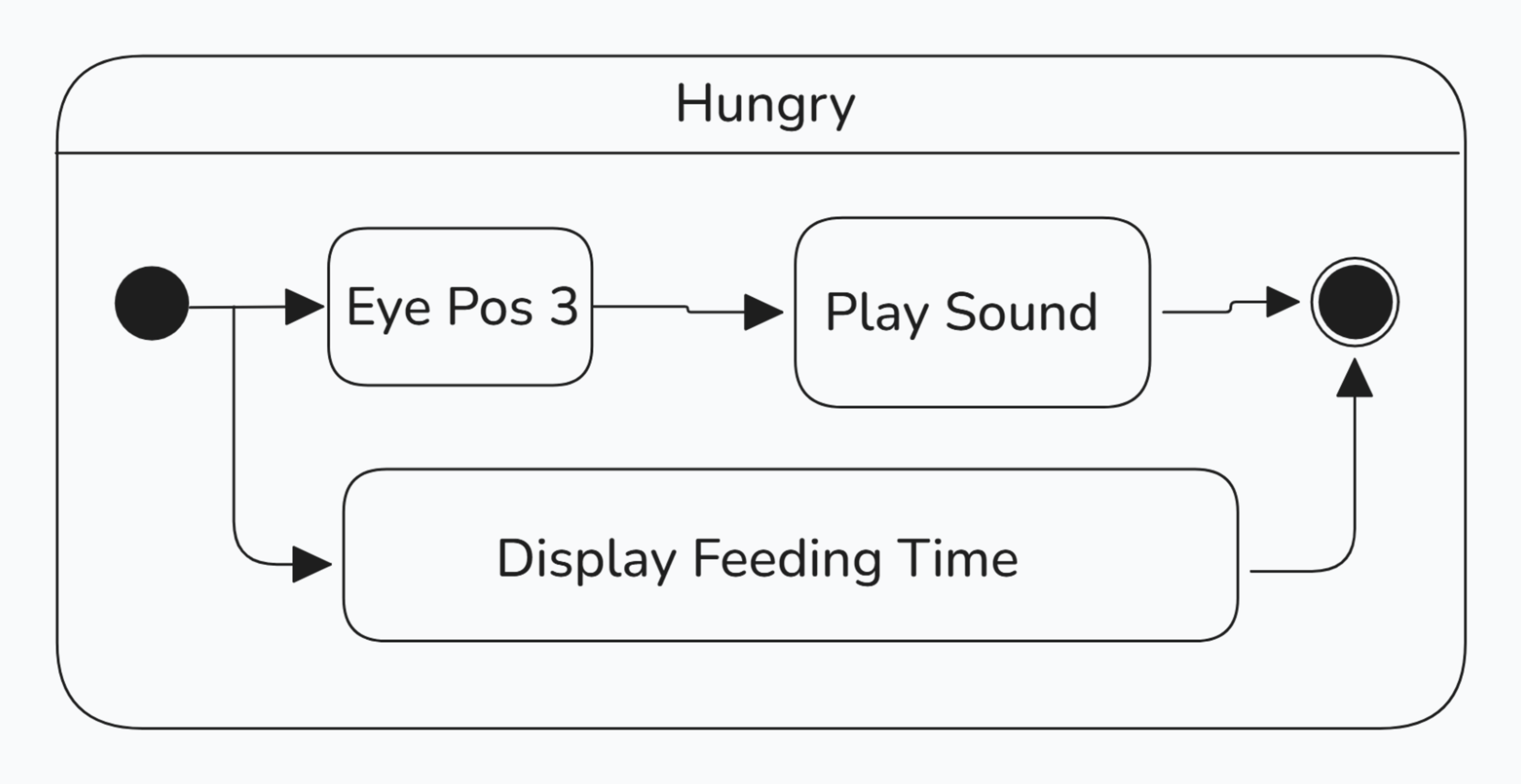
The monster will enter the hungry state if the health value drops below 30% of max health. Within the hungry state, the time can again be set and displayed. While in the hungry state, the monster’s tongue will wag and it’ll make a distinct sound. To exit the hungry state, the monster can either go to sleep when the lights are turned off, where it will continue to lose health. Or it can be fed by setting up a Hall Effect sensor. When fed, the health of the monster increases its health by 20 points. The monster can be overfed if it is currently in a happy state, where it will gain a feed counter. While feeding the monster, the monster’s eye will be closed, the mouth will appear open, and a distinct sound will be played.

The Sleepy state can be entered anytime from the Happy, Content, or Hungry states. The Sleepy state is entered once the ambient lighting becomes low. The monster remains in the Sleepy state while the ambient lighting remains low.
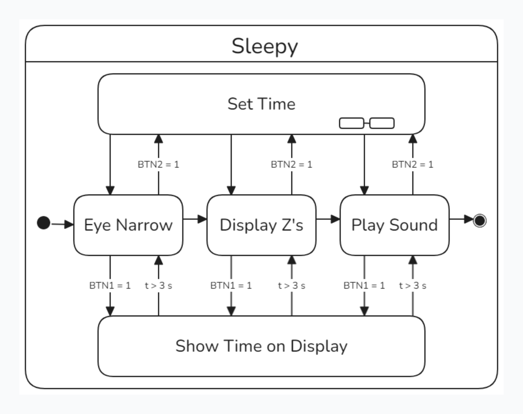
While in the sleepy state, the monster’s eye narrows, Z-s are displayed on the screen, and the monster makes a sound.
Software Implementation
The software implementation for the interactive mimic creature system involves several key modules that manage the system’s states, sensor inputs, actuator controls, and display updates.
Software Development Environment and Tools
The software was developed using Keil IDE, with the programming language being C.
System Initialization and State Machine
The firmware starts by bringing every peripheral to a known state, restoring persistent data, and then entering a state machine that drives all behaviour.
Initialization sequence
int main(void)
{
    __disable_irq();                // mask all interrupts while hardware comes up

    hallEffect_pinInit();
    Display_Init();
    I2C_init();
    Encoder_init();
    stepper_init();

    TIM1_setup();
    tim5_init();
    Timer6_Init();
    Timer7_Init();
    adc_init();
    sonar_gpio_init();
    WDT_init();                     // watchdog at ~32 s timeout

    __enable_irq();

    menu  = mainMenu;               // show main-menu first
    health = 7;                     // 70 % of a 10-point scale
    health_ptr = &health;

    HealthCurrent();                // draw health bar
    Init_seq();                     // power-on animation

    Store_Current_Health();         // seed EEPROM
    Retrieve_Health();              // reload if a value already exists
Key points:
- Global peripherals are initialised before interrupts are re-enabled.
-
healthis seeded to 70 %, then immediately written to and read back from EEPROM so future resets restore the same value. - The UI starts in
mainMenu; once the user exits, the state machine drops into the default content state.
Behavioural state machine
while (1)
{
    /* …house-keeping and watchdog refresh… */

    switch (state)
    {
        /* neutral baseline */
        case content:
            if (lightLvl <= 2) {                 // dark → sleepy
                state = sleepy;
                menu  = ExpSleepy;
                Play_Tone_2();
                Eyelid_Move_To(2570);            // close eyelids
                Expression_Transition = true;
                break;
            }

            if (health >= 5) {                   // well-fed → happy
                state = happy;
                menu  = ExpHappy;
                Play_Tone_1();
                Eyelid_Move_To(1500);            // open eyelids
                Expression_Transition = true;
                break;
            }

            if (health <= 2) {                   // starving → hungry
                state = hungry;
                menu  = ExpHungry;
                Play_Tone_3();
                Eyelid_Move_To(2200);            // half-closed
                Expression_Transition = true;
                break;
            }
            /* stays in content otherwise */
            break;

        case happy:
        case hungry:
        case sleepy:
        case dead:
        case MENU_STATE:
            /* see full listing for transition rules */
            break;
    }

    MENU_SCREENS();                // refresh TFT if a menu is active
}
Highlights:
-
contentis the default mood; other states fire when sensor-driven conditions are met. - Transitions depend on ambient light (
lightLvl), current health, and interaction flags (petFlag,Mimic_Servo.is_close). - Each transition updates the LCD expression, plays a short tone, and positions the eyelid servo, all through one flag (
Expression_Transition) so the heavy drawing calls execute exactly once per change.
This simple, event-driven structure keeps the main loop short while providing rich, immediate feedback to the user.
Proximity and Sensor Handling
The mimic monitors two classes of input:
- an ultrasonic rangefinder that detects how close a hand (or other object) is
- two Hall-effect sensors—one mapped to feeding, the other to petting
These sensors update lightweight flags (Mimic_Servo.is_close, petFlag) that other tasks consult to select expressions, move servos, and manage the health timer.
Ultrasonic rangefinder
/* main loop — evaluate distance every iteration */
distance = abs(dist());          // mm

if (distance < 400)              // inside 40 cm
    Mimic_Servo.is_close = true; // enable “close” behaviour
else
    Mimic_Servo.is_close = false;
The flag adds context to periodic actions. For example, the tongue only wags when the user is near (or actively petting):
/* TIM5_IRQHandler — fires once per second */
tongue_wag = tongue_wag ? 0 : 1;                 // alternate position

if (Mimic_Servo.is_close || petFlag)             // proximity OR petting
    Tongue_Move_To(tongue_wag ? 1000 : 2000);    // servo sweep
Hall-effect petting and feeding
/* EXTI15_10_IRQHandler — shared ISR for both Hall sensors */

if (EXTI->PR & (1 << HALL_PIN)) {   // feeding magnet
    HealthPlusPlus();               // +1 health point
}

if (EXTI->PR & (1 << HALL2_PIN)) {  // petting magnet
    petFlag = 1;                    // start 3 s “happy” window
    Play_Tone_1();                  // positive audio feedback
}

/* clear pending bits */
EXTI->PR |= (1 << HALL_PIN) | (1 << BTN1_PIN) | (1 << HALL2_PIN);
Feeding immediately boosts the health bar and resets the decay timer, while petting signals the state machine to enter or extend the happy expression.
Interaction with the state machine
-
Mimic_Servo.is_closeinfluences servo animations (eye tracking, tongue wag) and helps the pet decide whether to engage. -
petFlagkeeps the pet in the happy state for three seconds (Time_New – Time_Old > 3000). - Health additions from feeding push the pet toward happy; health depletion (when the ultrasonic flag is low and no petting occurs) moves the pet toward hungry or dead.
Together, these concise sensor handlers let the main loop remain simple while keeping the mimic lively and responsive.
Display Management
The firmware drives two independent visual outputs:
- a 320 × 240 RGB TFT used for menus, expressions, and real-time clock
- a dual-digit seven-segment module that shows the 60 s activity timer
TFT-LCD graphics
The display library is initialised once at boot:
Display_Init(); // GPIO, SPI, reset‐pulse, orientation
Every expression state supplies its own bitmap. When the state changes, the flag Expression_Transition gates a one-time redraw:
/* ExpContent branch inside MENU_SCREENS() */
if (Expression_Transition) {
    Rotate_Display(0);
    Fill_Screen(BROWN);                                    // wipe
    Draw_Bitmap((TFT_WIDTH  - contentImage->width) / 2,
                (TFT_HEIGHT - contentImage->height) / 2,
                contentImage);                             // centred
    Expression_Transition = false;
}
The same helper set (Rotate_Display, Fill_Screen, Draw_String_BG, Draw_Char_BG) is reused by the on-device menu system:
/* main menu layout */
Fill_Screen(BROWN);
Draw_String_BG(50,  80, "Time Set:", WHITE, BROWN, &font_ubuntu_mono_24);
Draw_String_BG(50, 120, "Help:",     WHITE, BROWN, &font_ubuntu_mono_24);
Draw_String_BG(50, 160, "More Info:",WHITE, BROWN, &font_ubuntu_mono_24);
Draw_String_BG(50, 200, "Cancel",   WHITE, BROWN, &font_ubuntu_mono_24);
A light-weight cursor is drawn by toggling a single character cell as the rotary encoder moves.
Seven-segment countdown
count holds the remaining seconds in the activity window (0 – 60). Whenever its value changes, the pair of digits are rewritten:
/* main loop */
if (count != old_count) {
    old_count = count;
    sevenSeg_write(0x05, num[count / 10]);  // tens
    sevenSeg_write(0x04, num[count % 10]);  // ones
}
TIM5_IRQHandler decrements the counter once per second and rolls it over:
/* 1 Hz interrupt */
count--;
if (count <= 0) {
    count = 60;              // restart minute
    HealthMinusMinus();      // decay health bar
    Store_Current_Health();  // persist to EEPROM
}
Because the update happens in the background ISR, the main loop only performs the inexpensive digit refresh when the value actually changes, keeping CPU usage low while ensuring fluid visual feedback.
Time Setting and Health Management
Real-time clock adjustment with the rotary encoder
The encoder on TIM2 is used in quadrature mode for position and on EXTI4 for the push-button. Entering the Time Set menu (timMenu) resets the counter and limits its range so each detent maps to a single digit:
/* open Time Set menu */
TIM2->CNT = 0;            // start at the first digit
TIM2->ARR = 27;           // 14 positions → 0-13, encoded ×2
menu_flag = 1;            // stay in menu until user confirms
Each press toggles between cursor and value-edit modes:
/* EXTI4_IRQHandler — encoder push */
if (menu == timMenu) {
    if (swPress % 4 == 0)          // cursor mode
        TIM2->CNT = pos * 2;       // keep the highlight on the digit
    else                           // edit mode
        TIM2->CNT = value * 2;     // spin to change the digit

    if (pos == 13) menu_flag = 0;  // ‘Enter’ confirms
    if (pos == 12) {               // ‘Cancel’
        menu_flag = 0;
        RTC_Second = RTC_Minute = RTC_Hour =
        RTC_Date   = RTC_Month  = RTC_Year = 0;
    }
}
Digits are stored in timeDate[] while the user spins the knob; after menu_flag clears, they are packed BCD-style and written over I²C:
/* Set_TD() — final commit */
RTC_Second = timeDate[0]  << 4 | timeDate[1];
RTC_Minute = timeDate[2]  << 4 | timeDate[3];
RTC_Hour   = timeDate[4]  << 4 | timeDate[5];
RTC_Date   = timeDate[6]  << 4 | timeDate[7];
RTC_Month  = timeDate[8]  << 4 | timeDate[9];
RTC_Year   = timeDate[10] << 4 | timeDate[11];

Set_Time(RTC_Hour, RTC_Minute, RTC_Second);
Set_Date(RTC_Year, RTC_Month, RTC_Date);
Feeding countdown on the seven-segment display
count starts at 60 and decrements once per second in the TIM5 ISR:
void TIM5_IRQHandler(void)
{
    count--;
    if (count <= 0) {
        count = 60;              // restart minute
        HealthMinusMinus();      // decay by one unit
        Store_Current_Health();  // persist to EEPROM
    }
    TIM5->SR &= ~0x0001U;        // clear update flag
}
Whenever the value changes, the main loop redraws the tens and ones:
if (count != old_count) {
    old_count = count;
    sevenSeg_write(0x05, num[count / 10]);  // tens digit
    sevenSeg_write(0x04, num[count % 10]);  // ones digit
}
Feeding (Hall-effect sensor HALL_PIN) immediately bumps the health bar and leaves the countdown untouched, so the pet does not lose health again until the next full minute:
if (EXTI->PR & (1 << HALL_PIN)) {
    HealthPlusPlus();            // +1 health
}
By coupling an intuitive rotary interface for time entry with a visible countdown and health bar, the system gives clear, real-time feedback on both scheduling and the pet’s well-being.
Conclusion
This project demonstrated that a single STM32F446RETx microcontroller could unify sensors, actuators, persistent storage, and rich graphics into a cohesive experience. The mimic reliably tracked proximity, petting, feeding, ambient light, and time—transitioning through expressive moods while maintaining health logic and watchdog safety. Robust hardware abstraction and an interrupt-driven software architecture kept the main loop lightweight and responsive, enabling smooth servo motion, real-time audio–visual feedback, and seamless user input through the rotary encoder. The result was a fully self-contained digital pet.